INDEX
1. Preface
From April 1, 2025, SAN-EI will evaluate all SAN-EI AM Solar Simulators in accordance with “IEC 60904-9:2020” and our in-house standard “SAN-EI 2025-04”.
These standards also apply to the maintenance required to preserve the performance of SAN-EI AM Solar Simulators.
About “SAN-EI 2025-04”
Note: This document follows “IEC 60904-9:2020” and includes additional requirements specified in “SAN-EI 2025-04” where applicable.
・ Based on customer requests across various fields, we established this in-house standard in April 2025 to evaluate solar-simulator performance under conditions not fully addressed by conventional standards.
・ “SAN-EI 2025-04” was developed with reference to “IEC 60904-9:2020”.
・ The content will be updated in line with changes in international standards and customer requirements (the document name may also be updated accordingly).
・ Measurement and evaluation at SAN-EI are performed as follows:
・ “AM1.5G 300–1200 nm” is based on “IEC 60904-9:2020”.
・ “AM1.5G 300–1800 nm and 300–2200 nm” complies with “SAN-EI 2025-04”.
・ “300–1200 nm, 300–1800 nm and 300–2200 nm at AM0” comply with “SAN-EI 2025-04”.
・ Measurement and evaluation of AM1.5G and AM0 are performed as follows.
2. Setting “Reference Irradiance” for Measurement
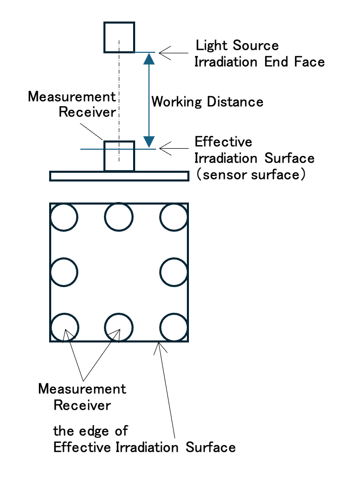
◆Measurement Receiver : Pyranometer or Reference Cell
・When “Effective Irradiation Surface” is □40 mm to □50 mm, we use Pyranometer.
・When “Effective Irradiation Surface” is □70 mm to □400 mm, we use Reference Cell.
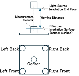
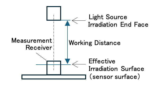
◆Measurement Position (Working Distance)
・Measurement Receiver is placed so that its light-receiving surface (sensor surface) is at Working Distance.
◆Measurement Position (on Irradiation Surface)
・Center of Effective Irradiation Surface
(Note)
Work Procedure
① Wait until Lamp turns on and becomes “Stable” (20 to 30 minutes).
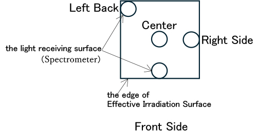
② Using Measuring Receiver, measure Irradiance at 5 points shown in the figure.
③ Non-uniformity among the 5 points is calculated as follows:
(Maximum − Minimum) / (Maximum + Minimum) × 100 (%)
④ Adjust Lamp Position so that the calculated value is 1.5% or less.
【AM1.5G】
⑤ Adjust Lamp Current so that Center Measurement Value becomes Sensitivity Constant.
◆Reference Irradiance
・1000 W/m²(±5%)
・Irradiance is adjusted based on Sensitivity Constant.
【AM0】
⑤ Adjust Lamp Current so that the receiver output (voltage) at the center becomes 1.20 × V₁₀₀₀,
where V₁₀₀₀ is the output at 1000 W/m² under AM1.5G using the same receiver.
◆Reference Irradiance
・1348 W/m²(±5%) —-This value is defined as “1 SUN of AM0”.※❶
・Adjust Irradiance so that Output Voltage of Measurement Receiver is 1.2 times Sensitivity Constant.※❷
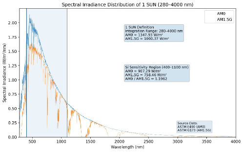
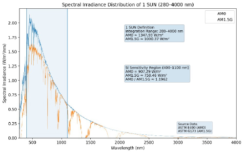
※❶ Reason why “1 SUN of AM0” is “1348 W/m²”
It is well known that “1 SUN of AM1.5G” is “1000 W/m²”.
This is “Total Radiant Energy Value from 280 to 4000 nm” based on “ASTM G173-03.”
(”ASTM G173-03″ is data on AM1.5G Radiant Energy.)
Similarly, “Total Radiant Energy from 280 to 4000 nm” of “ASTM E-490” is “1348 W/m².”
(”ASTM E-490″ is data for AM0 Radiant Energy.)
※❷ Reason for setting “1.2 times Sensitivity Constant as 1 SUN of AM0”
・There is no dedicated Measuring Device for Measuring AM0 Light.
・Reference Cells and Pyranometers (silicon type) can only measure in 400-1100 nm range.
・Total Radiant Energy Value of “ASTM G173-03” in “400-1100 nm” range is “759 W/m²”.
・Total Radiant Energy Value of “ASTM E-490” in “400-1100 nm” range is “908 W/m²”.
・「908 W/m²」÷「759 W/m²」=1.20
・Radiant Energy of AM0 at “400-1100 nm” is 1.2 times that of AM1.5G.
・Therefore, “Radiant Energy that is 1.2 times Sensitivity Constant of Measuring Receiver”is defined as “1348 W/m².”
(Note)
It only applies to Light with “Spectral Match of 75-125%.”
3.Spectral Match
(1)Preparation before Measurement
◆Measurement Receiver : Pyranometer or Reference Cell
・When “Effective Irradiation Surface” is □40 mm to □50 mm, a Pyranometer is used.
・When “Effective Irradiation Surface” is □70 mm to □400 mm, a Reference Cell is used.
◆Measurement Position (Working Distance)
・Measurement Receiver is placed so that its light-receiving surface (sensor surface) is at Working Distance.
◆Measurement Position (on Irradiation Surface)
・Center of Effective Irradiation Surface
◆Reference Irradiance
【AM1.5G】
・1000 W/m²(±5%)
・Irradiance is adjusted based on Sensitivity Constant.
【AM0】
・1348 W/m²(±5%)
・Adjust Lamp Current so that the receiver output (voltage) at the center becomes 1.20 × V₁₀₀₀,
where V₁₀₀₀ is the output at 1000 W/m² under AM1.5G using the same receiver.
(2)Measurement and Recording
◆Using Spectrometer, measure and record Irradiance in the range 300–2200 nm at 1 nm intervals.
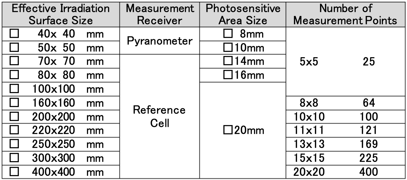
◆Measurement positions are as follows:
・When Effective Irradiation Surface is □40 mm to □100 mm, only Center in the figure below.
・When Effective Irradiation Surface is □160 mm to □400 mm, 4 points in the figure below.
◆Except for Center, the light-receiving surface edge of Spectrometer is made to contact
Effective Irradiation Surface Edge.
(3)Organizing Measurements
◆Organize the data for each of 4 measurement points. (When Effective Irradiation Surface is □40mm-□100mm, only Center.)
◆Calculate Interval Sum for each Wavelength.
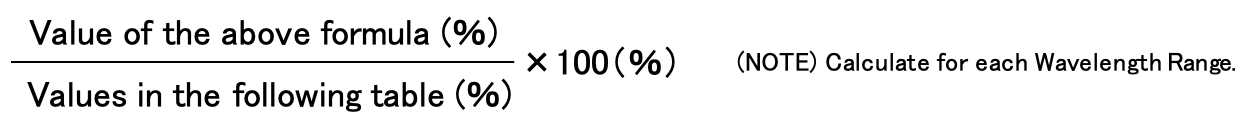
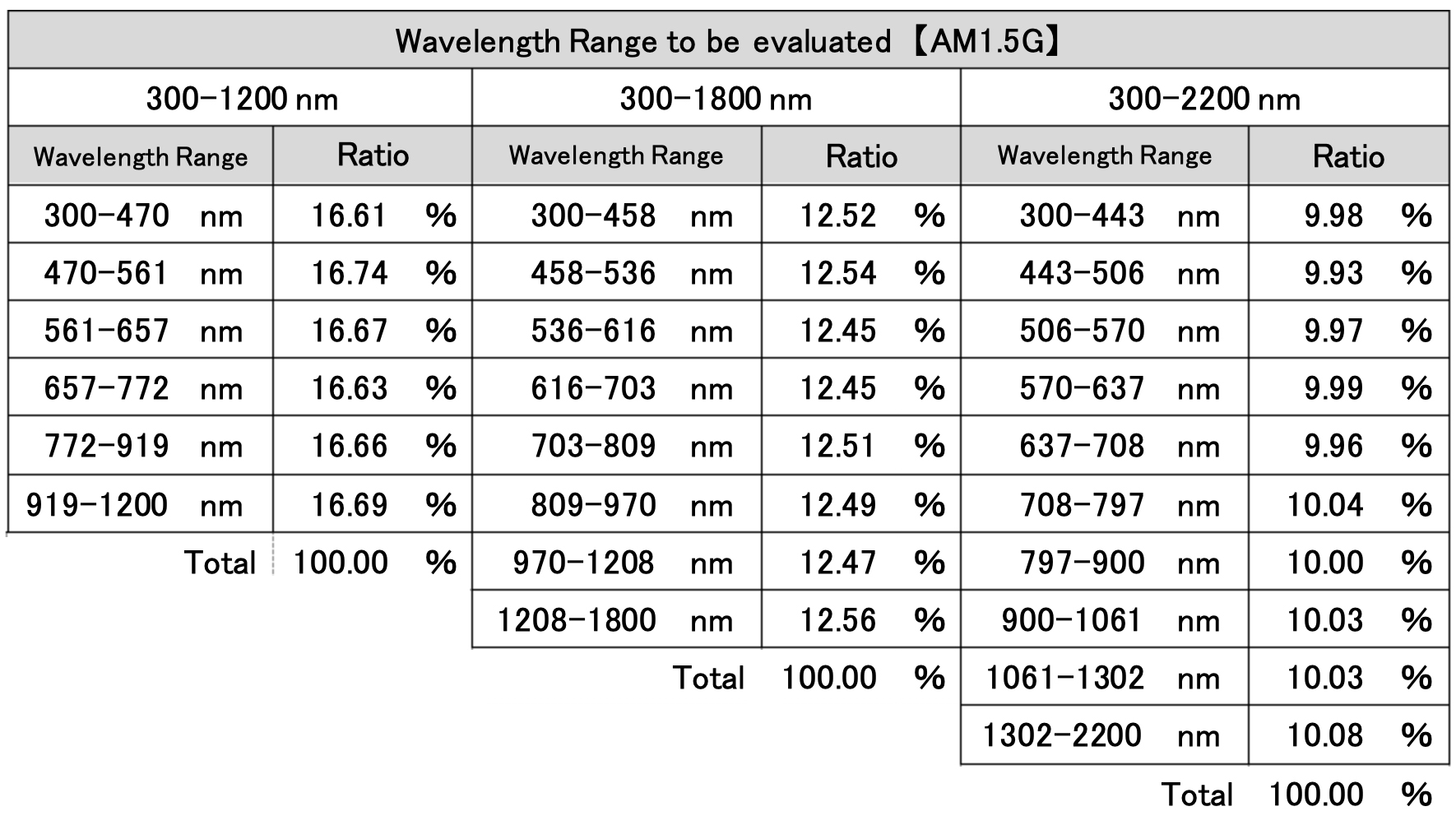
◆Calculate Sum of each Wavelength Range as shown in the table below.
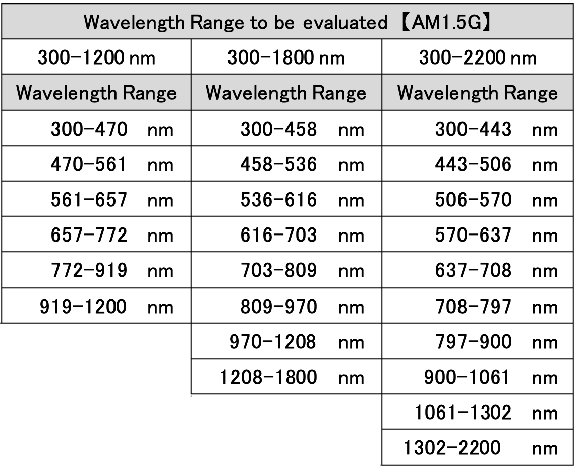
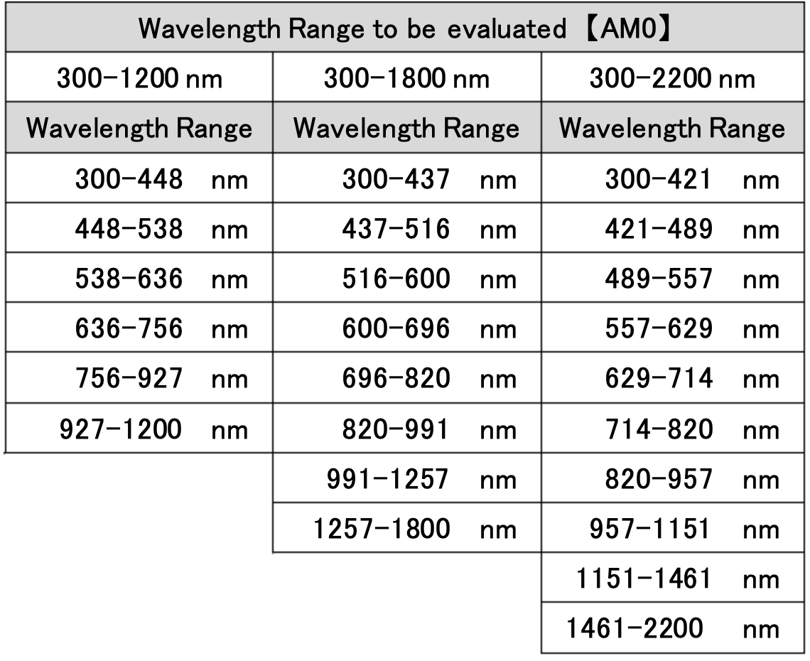
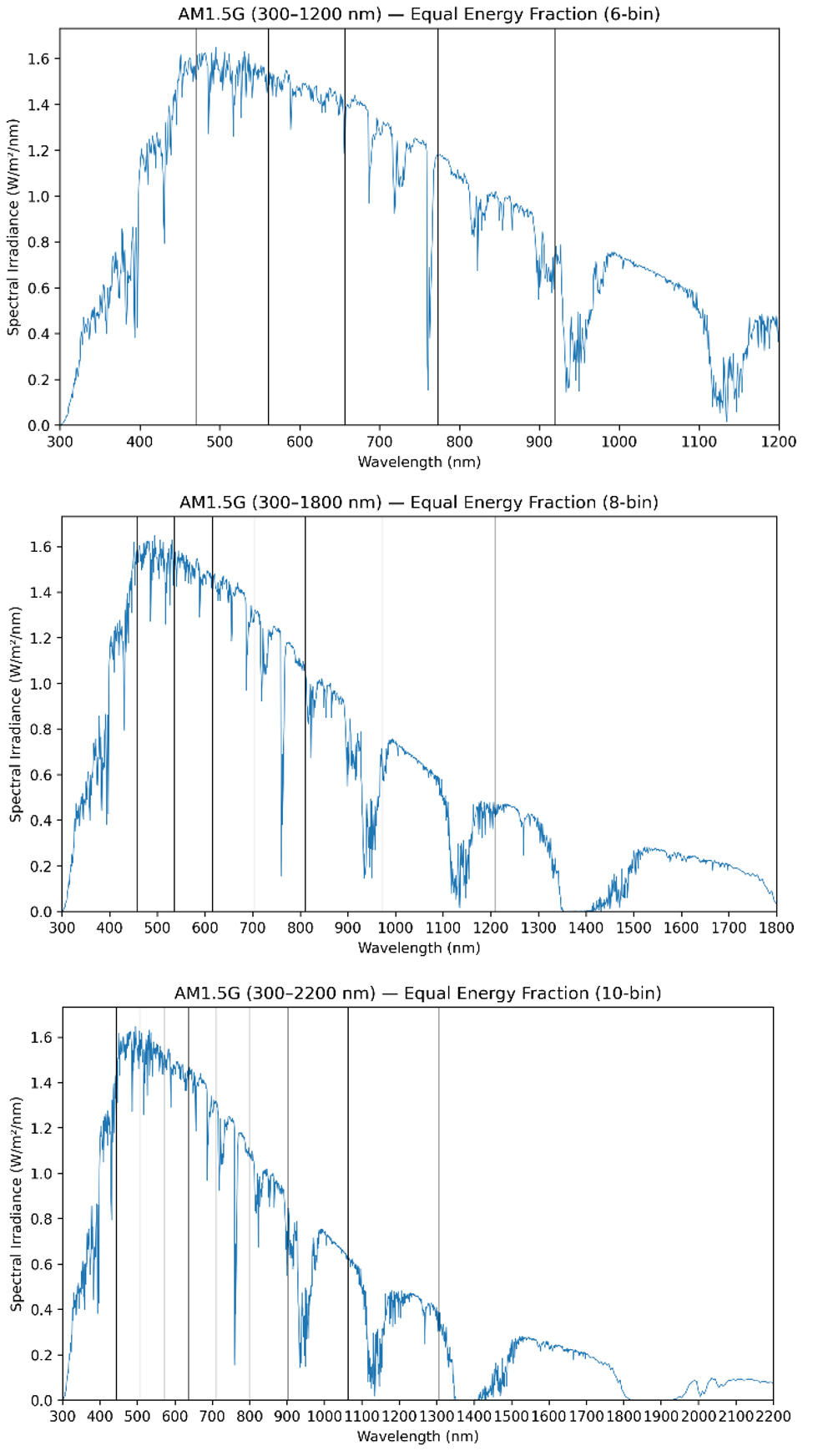
◆Calculate Percentage for each Wavelength Range using the following formula.

◆The following formula is used to calculate “Spectral Match”
◆Extract Minimum and Maximum values from “Spectral Matches” for each Wavelength Range.
◆Extract Minimum and Maximum values at each Measurement Position (1 or 4).
◆Minimum and Maximum of all measurements is taken as “Spectral Match” for that product.
(4)Evaluation
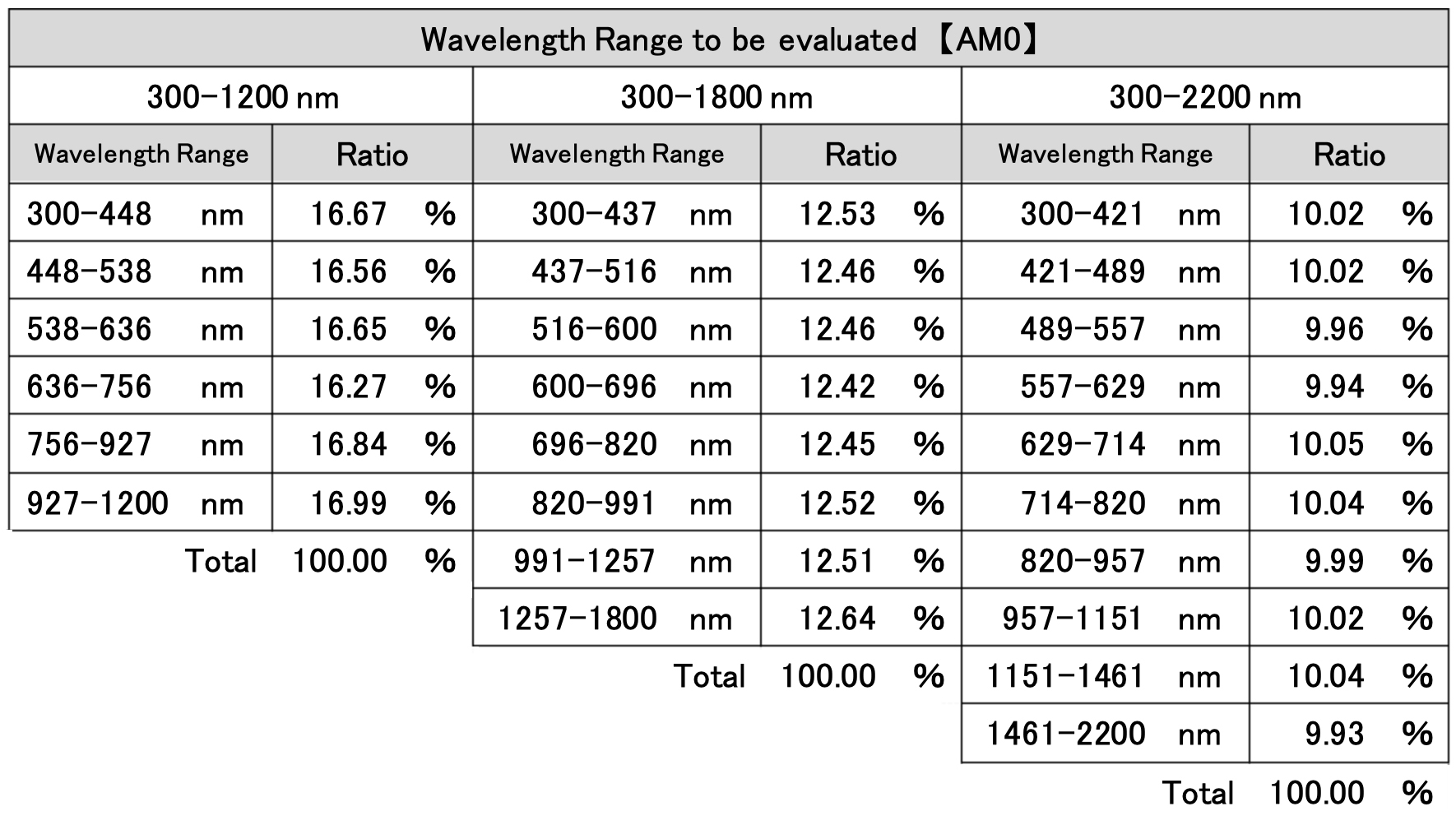
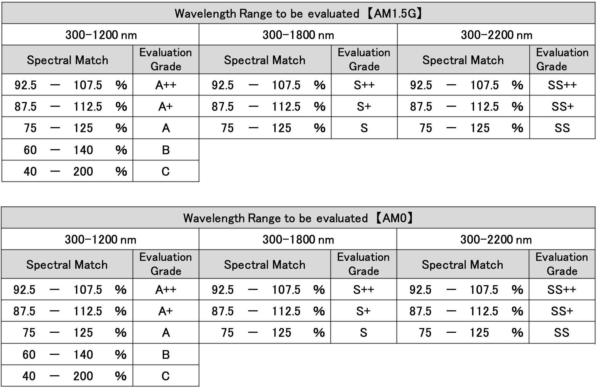
◆Range (Minimum to Maximum) of “Spectral Match” determined above is evaluated based on the table below.
(Note)
IEC-defined grades (AM1.5G, 300–1200 nm): A+, A, B, C. This document also defines A++ as an enhanced grade stricter than IEC A+.
SAN-EI-defined grades (300–1800 nm and 300–2200 nm): S/S+/S++ and SS/SS+/SS++.
for extended wavelength ranges (300–1800 nm and 300–2200 nm).
Grades B and C are IEC-compatible and apply only to the 300–1200 nm column.
4. Spatial Non-Uniformity of Irradiance
(1)Preparation before Measurement
◆Measurement Receiver : Pyranometer or Reference Cell
・When “Effective Irradiation Surface” is □40 mm to □50 mm, a Pyranometer is used.
・When “Effective Irradiation Surface” is □70 mm to □400 mm, a Reference Cell is used.
◆Measurement Position (Working Distance)
・Measurement Receiver is placed so that its light-receiving surface (sensor surface) is at Working Distance.
◆Measurement Position (on Irradiation Surface)
・Center of Effective Irradiation Surface
◆Reference Irradiance
【AM1.5G】
・1000 W/m²(±5%)
・Irradiance is adjusted based on Sensitivity Constant.
【AM0】
・1348 W/m²(±5%)
・Adjust Lamp Current so that the receiver output (voltage) at the center becomes 1.20 × V₁₀₀₀, where V₁₀₀₀ is the output at 1000 W/m² under AM1.5G using the same receiver.
(2)Measurement and Recording
◆Measurements shall be performed as specified in the table below.
◆Measurement Receiver is placed so that its light-receiving surface is at Working Distance.
◆Measurement Position (on Irradiation Surface)
・Measure 25 to 400 points as shown in the table below.
(Note) Align the edge of the light-receiving surface of Measurement Receiver
with the edge of Effective Irradiation Surface.
◆The reading on Measurement Receiver(output voltage) will fluctuate slightly, so record Intermediate Value.
(3)Organizing Measurements
◆Extract Minimum and Maximum Output Voltage from Measurement Receiver
◆Calculate “Irradiance non-uniformity” using the following formula.
(Maximum − Minimum) / (Maximum + Minimum) × 100 (%)
◆Create a chart
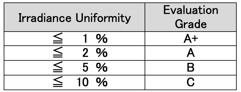
(4)Evaluation
◆”Irradiance non-uniformity” calculated using the above formula
is evaluated based on the table below.
5. Temporal Instability of Irradiance
(1)Preparation before Measurement
◆Measurement Receiver : Pyranometer or Reference Cell
・When “Effective Irradiation Surface” is □40 mm to □50 mm, a Pyranometer is used.
・When “Effective Irradiation Surface” is □70 mm to □400 mm, a Reference Cell is used.
◆Measurement Position (Working Distance)
・Measurement Receiver is placed so that its light-receiving surface (sensor surface) is at Working Distance.
◆Measurement Position (on Irradiation Surface)
・Center of Effective Irradiation Surface
◆Reference Irradiance
【AM1.5G】
・1000 W/m²(±5%)
・Irradiance is adjusted based on Sensitivity Constant.
【AM0】
・1348 W/m²(±5%)
・Adjust Lamp Current so that the receiver output (voltage) at the center becomes 1.20 × V₁₀₀₀,
where V₁₀₀₀ is the output at 1000 W/m² under AM1.5G using the same receiver.
(2)Measurement and Recording
◆Short Term Instability (STI)
・Measured 30 minutes after the lamp is switched on
・Measurement Interval : 1/1000 seconds
・Measurement Time (number of times) : 1 second (1000 times)
・Measurement and Recording using Measurement Receiver and Data Logger
◆Long Term Instability (LTI)
・Measured 30 minutes after the lamp is switched on
・Measurement Interval : 1/2 seconds
・Measurement Time (number of times) : 1 hour (7200 times)
・Measurement and Recording using Measurement Receiver and Data Logger
(3)Organizing Measurements
◆Extract Minimum and Maximum Output Voltage from Measurement Receiver
◆Calculate “Temporal Instability” using the following formula.
(Maximum − Minimum) / (Maximum + Minimum) × 100 (%)
◆Create a chart
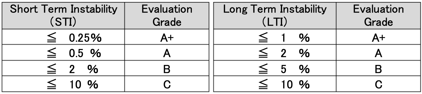
(4)Evaluation
◆”Temporal Instability” calculated using the above formula is evaluated based on the table below.